
Introducing the Remote I/O Unit,
Which Allows You to Easily Expand the Number of I/O Points on the Controller
- Capable of Expanding the Number of I/O Points on the Controller
- Small Product Size Easy Installation with DIN Rails
- Easy Connection and Less Cables
- The Front Panel LED Lights Make Unit Status Apparent
- Compatible Controllers
Capable of Expanding the Number of I/O Points on the Controller
The remote I/O units have input-only model (IN specification) and output-only model (OUT specification), and each are equipped with 32 I/O points. You can install a maximum of 8 units (Note 1) each of the IN specification and OUT specification models, for a total of 16 units. The maximum expansion is 256 points (Note 1) for input and 256 points for output.
 Note 1: In the case of SSEL (MSEL and TTA allow a maximum of 7 units each, with 224 points each of input and output points)
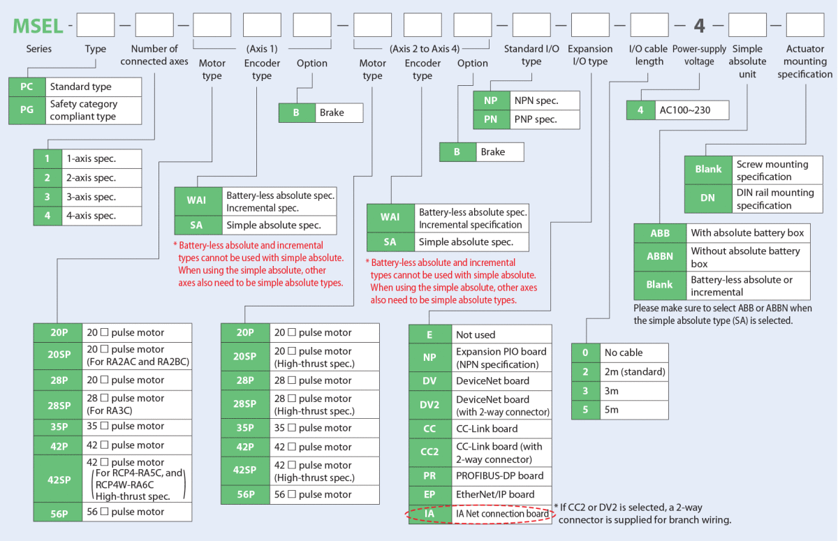
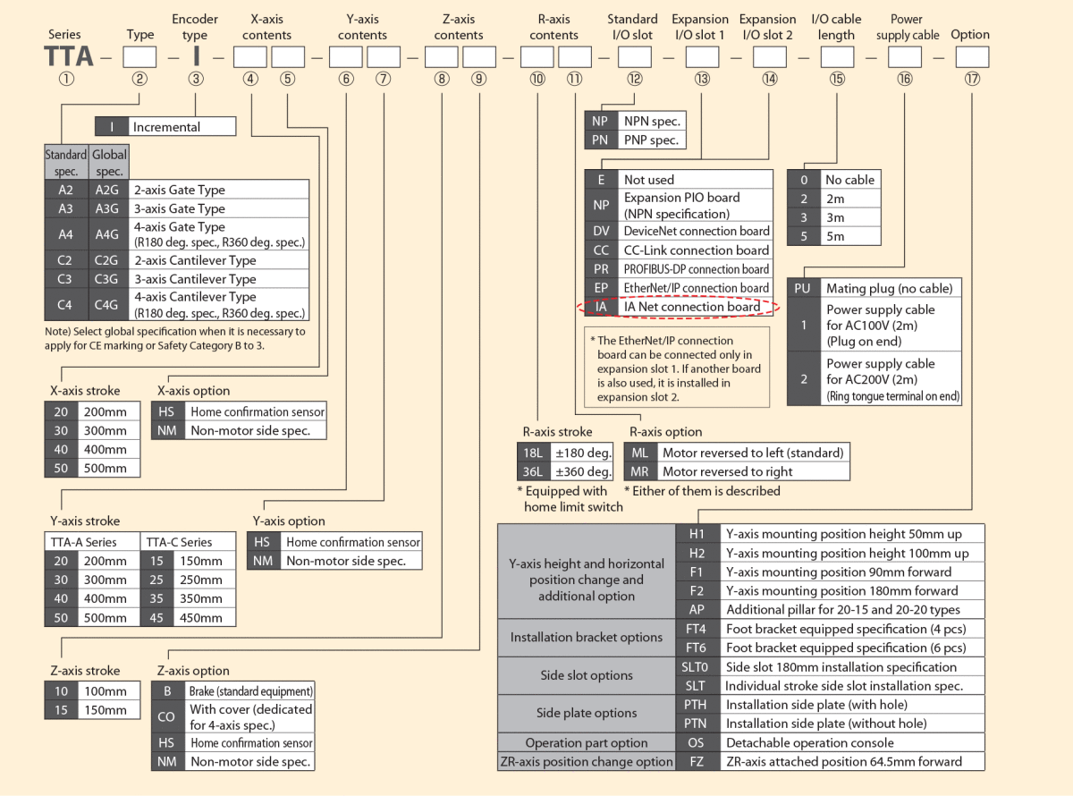
Note 2: There are two units of the terminal resistance enclosed if IA (IA Net connection board) is selected in the I/O type in the controller model code.

Small Product Size Easy Installation with DIN Rails
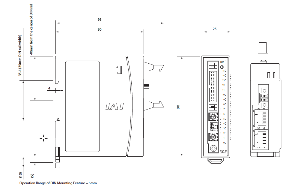
The product size is very compact at 25mm (Width) by 90mm (Height) by 98mm (Depth). Installation is very simple using DIN rail mounts.
Easy Connection and Less Cables
Connection between the controller and remote I/O units and among remote I/O units can be conducted with general LAN cables (with Category 5 or higher).

■ When Remote I/O Units Are Not Used
As the connection between the controller and the terminal block is to be conducted with I/O cable, it is necessary to pay attention to the wiring layout of the cable.

■ When Remote I/O Units Are Used
I/O cable can be short, and the connection between the controller and I/O units can be conducted with just one LAN cable, which makes the wiring layout nice and tidy.
The Front Panel LED Lights Make Unit Status Apparent
 The status of the unit can be checked on the status LED lamps mounted in the front panel.
■ PIO input terminal status
■ PIO output terminal status
■ Error status, etc.
Compatible Controllers

The remote I/O unit is compatible with three controllers: the SSEL, MSEL, and TTA.
Model List
| Name | Remote I/O Unit | |
| Type | Input Unit (IN Specification) | Output Unit (OUT Specification) |
| External View | ||
| Standard Price | - | - |
Model Code

Specifications
| Items | Specifications (IN /OUT) |
| Rated Voltage | DC24V |
| Operating Voltage Range | DC21.6 ~ 26.4V |
| Current Consumption | IN: 0.16A max. / OUT: 1.6A max. |
| Number of I/O Points | IN: 32 points / OUT: 32 points |
| Communication Method | Half-duplex multi-drop |
| Baud Rate | IN: 12mbps / OUT: 3mbps |
| Number of Connectable Units | IN: 8 units max. / OUT: 8 units max. (SSEL) IN: 7 units max. / OUT: 7 units max. (MSEL & TTA) |
| Communication Cycle Time | IN: 0.627msec (baud rate: 12mbps) OUT: 2.508msec (baud rate: 3mbps) |
| Total Cable Length (IA Net Connection) | IN: 100m (baud rate: 12mbps) OUT: 300m (baud rate: 3mbps) |
| Size | 25mm (W) × 90mm (H) × 98mm (D) |
| Weight | 87g |
| Electric Shock Protection | Class1 basic insulation |
| Insulation Resistance | DC500V 10mΩ |
| Installation Method | DIN rail mount |
| Ambient Operating Temperature | 0 ~ 40°C |
| Ambient Operating Humidity | 20 ~ 85% RH (non-condensing) |
Part Names

I/O connector
This connector allows 32 points of input or output control signals to be connected.
![]()
Station address setting switch (SA rotary switch)
This sets the station address. For both the IN and OUT specifications, you can set the position of the rotary switch starting from 0 and up.
![]()
Main unit setting DIP switch
Switch 1 sets the baud rate of the network.
![]()
Status LED 1 display changeover rotary switch (STS rotary switch)
This changes the information displayed on Status LED 1.
![]()
FG grounding terminal
This is a terminal to connect the grounding line to prevent electric shock and noise.
![]()
Main unit setting confirmation LED
This will turn on in green while main unit setting confirmation switch is pressed.
Main unit setting confirmation switch
After changing the position of the stationary address switch or the baud rate setting switch, pressing this switch will make the changes effective. There is no need to reboot the unit.
![]()
Status LED 1
This displays the status of the product in response to the position set with STS rotary switch. Refer to the instruction manual for details.
![]()
Status LED 2
This displays the normal / error status in the communication. Refer to the instruction manual for details.
![]()
Status LED 3
Positions of STS rotary switch are displayed with RS0, RS1 and RS2 LED lamps. Refer to the instruction manual for details.
![]()
24V Power supply connector
This is a connector to supply DC24V power to the controller.
![]()
IA Net connector
This connects an IA Net communication cable or terminal resistor. Please connect a terminal resistor to the master controller or remote I/O unit that will be the end of the network.


