


Stroke and maximum speed
(Unit: mm/s)
| stroke Lead |
25 (mm) |
50 (mm) |
75 to 150 (mm) |
|
|---|---|---|---|---|
| Slide screw | 6 | 180 | 280 | 300 |
| 4 | 180 | 200 | ||
| 2 | 100 | |||
Adaptive Controller
The actuators on this page can be operated with the following controllers. Please select the type that suits your application.
| name | exterior | Maximum number of connectable axes |
Power supply voltage | Control Method | Maximum number of positioning points | ||||||||||||||
|---|---|---|---|---|---|---|---|---|---|---|---|---|---|---|---|---|---|---|---|
| Positioner | Pulse train | program | Network ※Select | ||||||||||||||||
| DV | CC | CIE | PR | CN | ML | ML3 | EC | EP | PRT | SSN | ECM | ||||||||
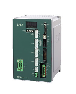 |
4 | Single phase AC 100-230V |
- | - | ● | ● | ● | - | ● | - | - | - | ● | ● | ● | - | - | 30000 | |
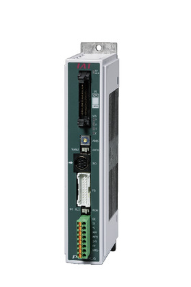 |
1 | DC24V | ● ※Select |
● ※Select |
- | ● | ● | ● | ● | ● | ● | ● | ● | ● | ● | - | - | 512 (network specification is 768) |
|
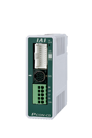 |
1 | ● ※Select |
● ※Select |
- | - | - | - | - | - | - | - | - | - | - | - | - | 64 | ||
 |
16 (ML3, SSN, ECM are 8) |
- | - | - | ● | ● | ● | ● | - | - | ● | ● | ● | ● | ● | ● | 128 (ML3, SSN, ECM no position data) |
||
 |
8 | - | - | ● | ● | ● | ● | ● | - | - | - | ● | ● | ● | - | - | 36000 | ||
(Note) For network abbreviations such as DV and CC, please see page
International Standards


Selection considerations
| (1) As the stroke becomes longer, the maximum speed decreases due to the critical rotation speed of the ball screw. Check the maximum speed for the stroke you want in "Stroke and Maximum Speed". (2) The maximum load capacity is shown in "Main Specifications". For details, refer to the "Load Capacity by Speed and Acceleration Table". (3) Can only be used in a horizontal position. (4) If used in a dusty environment, the lifespan will be significantly reduced. (5) This model uses a sliding screw (※) and sliding guide, so please use it in an application suitable for its characteristics. Please note that sliding guides cannot handle offset loads. (※ See page (6) Even when used with simple absolute, the encoder type column in the model item will be "I". |
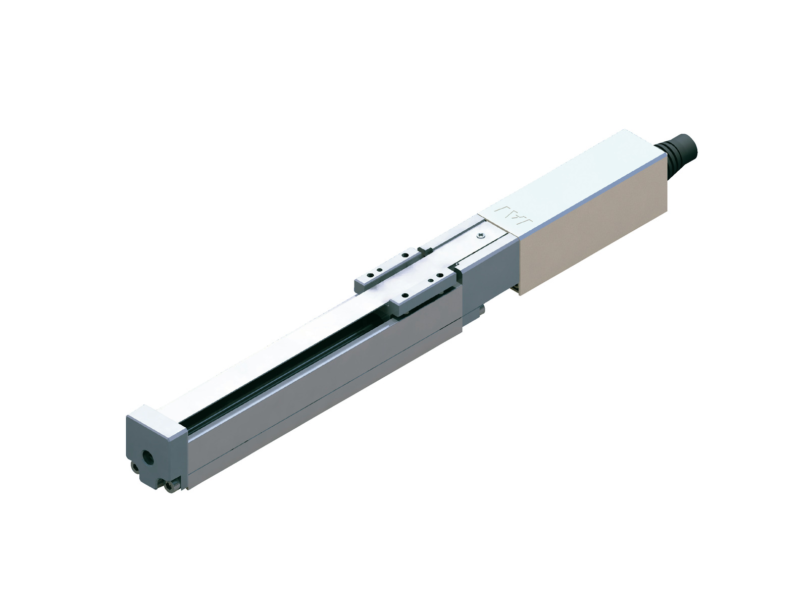
Dimensions
ST: Stroke
ME: Mechanical end
SE: Stroke end
(Note) The motor/encoder cable is connected to the cable joint connector. For details on the cable, see page
(Note) When returning to the origin, the slider moves to the ME, so be careful not to let it interfere with surrounding objects.
(Note) Pay attention to the length of the mounting bolts. When using mounting screws on the back of the base, if the bolts are long, they may interfere with the internal parts, causing abnormal sliding or damage to the parts.
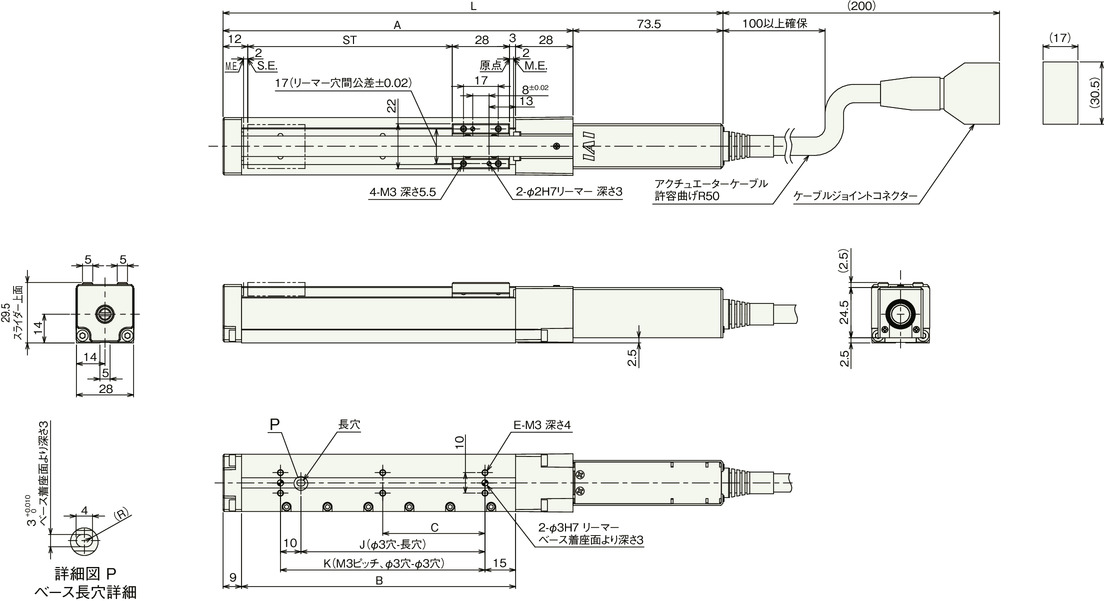
Stroke dimensions
| stroke | 25 | 50 | 75 | 100 | 125 | 150 |
|---|---|---|---|---|---|---|
| L | 169.5 | 194.5 | 219.5 | 244.5 | 269.5 | 294.5 |
| A | 96 | 121 | 146 | 171 | 196 | 221 |
| B | 59 | 84 | 109 | 134 | 159 | 184 |
| C | 0 | 0 | 0 | 50 | 62.5 | 75 |
| E | 4 | 4 | 4 | 6 | 6 | 6 |
| J | 15 | 40 | 65 | 90 | 115 | 140 |
| K | 25 | 50 | 75 | 100 | 125 | 150 |
Mass by stroke
| stroke | 25 | 50 | 75 | 100 | 125 | 150 |
|---|---|---|---|---|---|---|
| Mass (kg) | 0.3 | 0.32 | 0.35 | 0.37 | 0.4 | 0.42 |